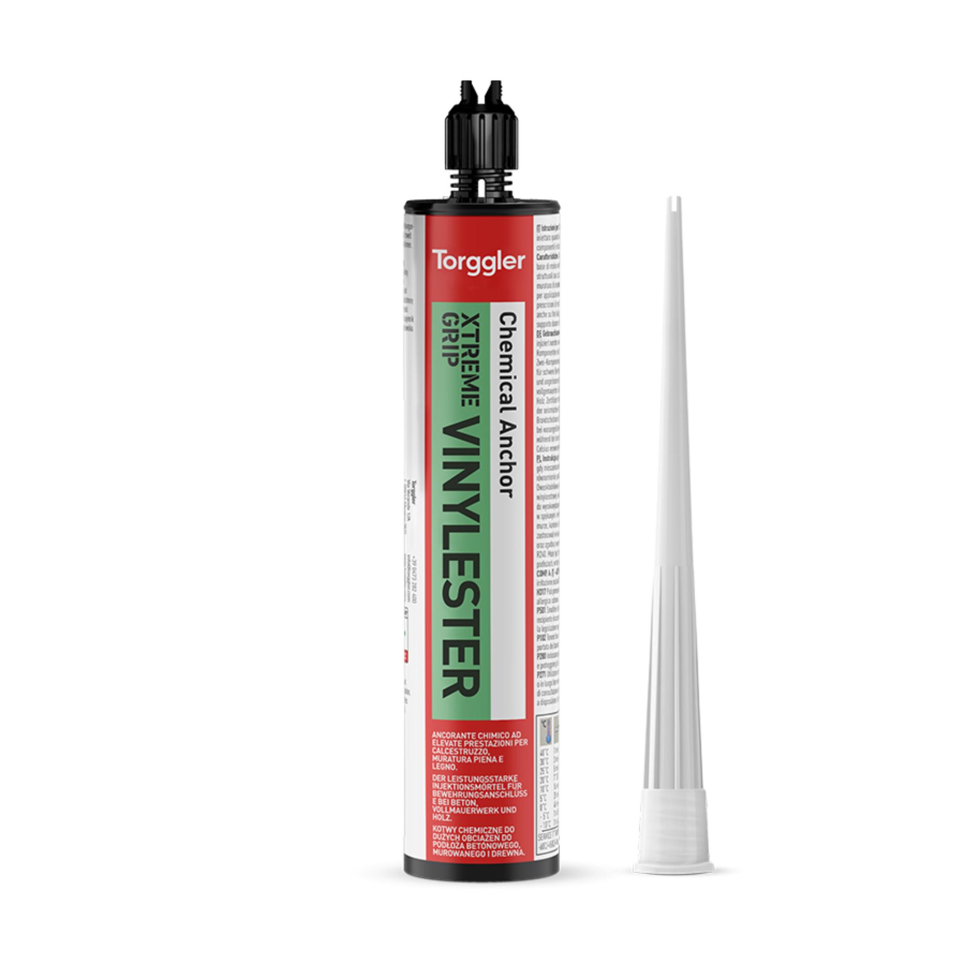
Xtreme Grip Vinylester
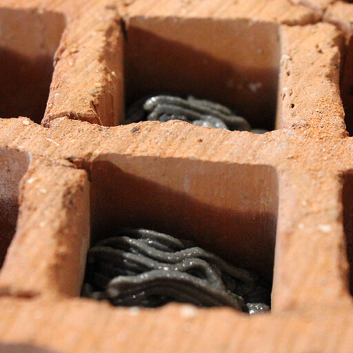
Two-component vinylester resin-based chemical anchor without styrene for structural fixings on cracked/un-cracked concrete, solid and perforated brick masonry, wood.
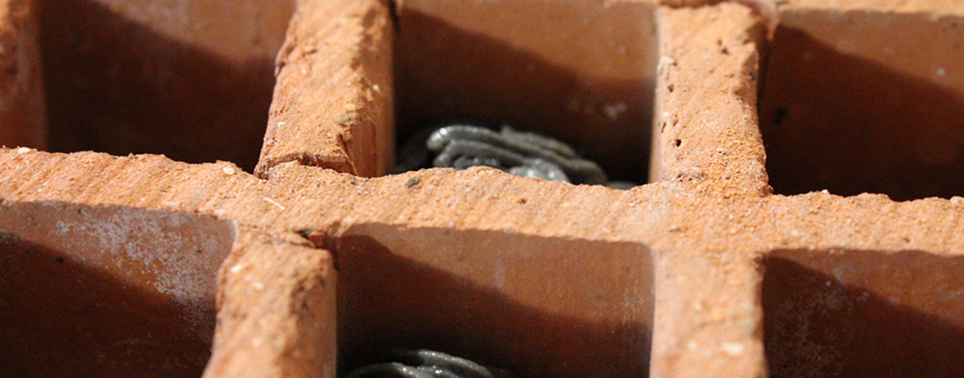
Two-component vinylester resin-based chemical anchor without styrene for structural fixings on cracked/un-cracked concrete, solid and perforated brick masonry, wood.


Discover more
Two-component, styrene-free, vinylester resin-based chemical anchoring agent for structural fixing of heavy loads on cracked/non-cracked concrete, solid and hollow brick masonry, timber. Thanks to its fast hardening, it can be used where there is a need for quick commissioning and in any case for anchors with a sinking depth of up to 1 metre. It can be applied even if the temperature of the substrate reaches critical values (-10 to +40 °C). In case of wet substrates and with flooded hole, the certification includes the use of threaded rods and in any case the loading time will be double. The product, depending on the diameter of threaded rods or improved adhesion rods used, is qualified according to the European Technical Assessment (ETA) for applications on cracked concrete (option 1), non-cracked concrete (option 7), even if the work falls under seismic category C1 C2.
Store between +5 and +30 °C, away from UV rays. When stored in a dry and covered place in its original sealed packaging Xtreme Grip Vinylester is stable for:
Do not use the product:
In case of doubt, contact our Technical Department.
| Code | Bicomponent | Packaging | Packaging size | Pallet | Barcode |
|---|---|---|---|---|---|
| 8051 | 2 components | cartridge | 12x300 ml |
72 cardboards
|

|
| 8052 | 2 components | cartridge | 12x400 ml |
52 cardboards
|

|
Combined with threaded rods or improved adhesion rods, it can be used for many cases of heavy load fastening or where, due to the presence of critical temperatures (< 0 °C or > 30 °C), the use of other types of anchors is impossible. Thanks to its styrene-free chemistry it can be used in closed environments as well.
FIXING ON CONCRETE WITH THREADED RODS
The approval, according to EAD 330499-01-0601, is valid for a wide range of threaded rods (from M8 to M30) and for different anchoring depths even on wet concrete and with flooded hole.
The certified operating temperatures are within the ranges:
| ETA-19/0842 | Fixing of min. 5 µ grade 5.8 galvanized steel threaded rods on concrete C20/25 | |||||||||
| Characteristic dimensions | M8 | M10 | M12 | M16 | M20 | M24 | M27 | M30 | ||
| d0 |
Hole diameter | mm | 10 | 12 | 14 | 18 | 24 | 28 | 30 | 35 |
| Tinst | Tightening torque | Nm | 10 | 20 | 40 | 80 | 130 | 200 | 250 | 280 |
| Sw | Key | mm | 13 | 17 | 19 | 24 | 30 | 36 | 41 | 46 |
| df | Hole Ø in the object to be fixed | mm | 9 | 12 | 14 | 18 | 22 | 26 | 30 | 33 |
| Minimum anchoring depth | ||||||||||
| Characteristic dimensions | M8 | M10 | M12 | M16 | M20 | M24 | M27 | M30 | ||
| h1 | Hole depth | mm | 65 | 75 | 85 | 105 | 125 | 150 | 150 | 150 |
| hnom | Nominal anchoring depth | mm | 60 | 70 | 80 | 100 | 120 | 145 | 145 | 145 |
| hmin | Minimum thickness of base material | mm | 100 | 100 | 110 | 136 | 168 | 201 | 210 | 220 |
| Scr | Hole centre distance | mm | 180 | 210 | 240 | 300 | 360 | 435 | 435 | 435 |
| Ccr | Distance from the edge | mm | 90 | 105 | 120 | 150 | 180 | 218 | 218 | 218 |
| Smim | Minimum hole centre distance | mm | 40 | 50 | 60 | 75 | 100 | 115 | 120 | 140 |
| Cmin | Minimum distance from the edge | mm | 40 | 50 | 60 | 75 | 100 | 115 | 120 | 140 |
| Average anchoring depth | ||||||||||
| Characteristic dimensions | M8 | M10 | M12 | M16 | M20 | M24 | M27 | M30 | ||
| h1 | Hole depth | mm | 85 | 95 | 115 | 130 | 175 | 215 | 245 | 275 |
| hnom | Nominal anchoring depth | mm | 80 | 90 | 110 | 125 | 170 | 210 | 240 | 270 |
| hmin | Minimum thickness of base material | mm | 100 | 114 | 138 | 161 | 218 | 266 | 300 | 340 |
| Scr | Hole centre distance | mm | 240 | 270 | 330 | 375 | 510 | 630 | 720 | 810 |
| Ccr | Distance from the edge | mm | 120 | 135 | 165 | 187 | 255 | 315 | 360 | 405 |
| Smim | Minimum hole centre distance | mm | 40 | 50 | 60 | 75 | 100 | 115 | 120 | 140 |
| Cmin | Minimum distance from the edge | mm | 40 | 50 | 60 | 75 | 100 | 115 | 120 | 140 |
| Maximum anchoring depth | ||||||||||
| Characteristic dimensions | M8 | M10 | M12 | M16 | M20 | M24 | M27 | M30 | ||
| h1 | Hole depth | mm | 165 | 205 | 245 | 325 | 405 | 485 | 545 | 605 |
| hnom | Nominal anchoring depth | mm | 160 | 200 | 240 | 320 | 400 | 480 | 540 | 600 |
| hmin | Minimum thickness of base material | mm | 180 | 224 | 268 | 356 | 448 | 536 | 600 | 670 |
| Scr | Hole centre distance | mm | 480 | 600 | 720 | 960 | 1200 | 1440 | 1620 | 1800 |
| Ccr | Distance from the edge | mm | 240 | 300 | 360 | 480 | 600 | 720 | 810 | 900 |
| Smim | Minimum hole centre distance | mm | 40 | 50 | 60 | 75 | 100 | 115 | 120 | 140 |
| Cmin | Minimum distance from the edge | mm | 40 | 50 | 60 | 75 | 100 | 115 | 120 | 140 |
| Minimum anchoring depth | |||||||||
| Global safety factor applied | |||||||||
| Fixing on non-cracked concrete C20/25 with grade 5.8 threaded rods | |||||||||
| M8 | M10 | M12 | M16 | M20 | M24 | M27 | M30 | ||
| Traction | kN | 9,0 | 12,0 | 17,0 | 24,0 | 31,6 | 41,9 | 42,0 | 42,0 |
| Shear | kN | 5,4 | 8,6 | 12,5 | 23,3 | 36,3 | 52,5 | 68,2 | 83,4 |
| Average anchoring depth | |||||||||
| Global safety factor applied | |||||||||
| Fixing on non-cracked concrete C20/25 with grade 5.8 threaded rods | |||||||||
| M8 | M10 | M12 | M16 | M20 | M24 | M27 | M30 | ||
| Traction | kN | 9,0 | 12,0 | 17,0 | 24,0 | 31,6 | 41,9 | 42,0 | 42,0 |
| Shear | kN | 5,4 | 8,6 | 12,5 | 23,3 | 36,3 | 52,5 | 68,2 | 83,4 |
| Maximum anchoring depth | |||||||||
| Global safety factor applied | |||||||||
| Fixing on non-cracked concrete C20/25 with grade 8.8 threaded rods | |||||||||
| M8 | M10 | M12 | M16 | M20 | M24 | M27 | M30 | ||
| Traction | kN | 13,9 | 22,1 | 32,1 | 59,5 | 96,6 | 139,5 | 180,6 | 220,5 |
| Shear | kN | 8,3 | 13,2 | 19,2 | 35,7 | 58,0 | 83,7 | 108,8 | 133,1 |
| Minimum anchoring depth | |||||
| Global safety factor applied | |||||
| Fixing on cracked concrete C20/25 with grade 5.8 threaded rods | |||||
| M10 | M12 | M16 | M20 | ||
| Traction | kN | 9,1 | 12,2 | 17,1 | 22,5 |
| Shear | kN | 8,6 | 12,5 | 23,3 | 34,3 |
| Average anchoring depth | |||||
| Coefficiente di sicurezza globale applicato | |||||
| Fissaggio su CALCESTRUZZO C20/25 FESSURATO con barre filettate classe 5.8 | |||||
| M10 | M12 | M16 | M20 | ||
| Traction | kN | 11,7 | 17,8 | 23,9 | 33,8 |
| Shear | kN | 8,6 | 12,5 | 23,3 | 36,2 |
| Maximum anchoring depth | |||||
| Global safety factor applied | |||||
| Fixing on cracked concrete C20/25 with grade 8.8 threaded rods | |||||
| M10 | M12 | M16 | M20 | ||
| Traction | kN | 22,1 | 32,1 | 59,5 | 79,5 |
| Shear | kN | 13,2 | 19,2 | 35,7 | 58,0 |
| ETA-19/0841 | Fixing of improved adhesion rods on concrete | ||||||||
| Reinforcing rod diameter (mm) | Ø8 | Ø10 | Ø12 | Ø14 | Ø16 | Ø20 | Ø25 | Ø28 | Ø32 |
| Hole diameter (mm) | 12 | 14 | 16 | 18 | 20 | 25 | 30 | 35 | 40 |
| Maximum installation depth (mm) | 400 | 500 | 600 | 700 | 800 | 1000 | 1000 | 1000 | 1000 |
Minimum concrete cover: cmin = 30 mm + 0,06 lv ≥ 2 ∙ Ø per Ø < 25 mm
cmin = 40 mm + 0,06 lv ≥ 2 ∙ Ø per Ø ≥ 25 mm
Minimum hole centre distance between two post-installed rods: at = 40 mm ≥ 4 ∙ Ø
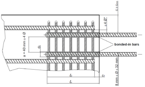
PROJECT LOADS – OF REBARS AS CONCRETE CASTING JOINTS
ETA-19/0841, PROJECT LOADS – OF REBARS AS CONCRETE CASTING JOINTS
Pre-calculated values for rebars anchoring.
Example of anchor length 1) with rods (f y,k = 500 N/mm2) on concrete C20/25 (fbd = 2.3 N/mm2).
1) The values given in the table refer to good adhesion conditions according to EN 1992-1-1. For all other conditions, multiply the values by 0.7.
2) The resin value can be estimated according to the equation V = lb π (d02-d2)/(4×0.85).
| a1 = a2 = a3 = a4 =a5 = 1,0 | a1 = a3 = a4 = 1,0 e e a2 o a5 = 0,7 |
||||||
| Rods Ø | Tensile load for rods Bst 500 | Anchor length lbd | Tensile load | Volume of resin V2) | Anchor length lbd | Tensile load | Volume of resin V2) |
| [mm] | [kN] | [mm] | [kN] | [ml] | [mm] | [kN] | [ml] |
| 8 | 21,85 | 115 | 6,65 | 8,50 | 115 | 9,50 | 8,50 |
| 180 | 10,40 | 13,31 | 180 | 14,86 | 13,31 | ||
| 250 | 14,45 | 18,48 | 200 | 16,52 | 14,78 | ||
| 320 | 18,50 | 23,65 | 220 | 18,17 | 16,26 | ||
| 378 | 21,85 | 27,95 | 265 | 21,85 | 19,56 | ||
| 10 | 34,15 | 145 | 10,48 | 12,86 | 145 | 14,97 | 12,86 |
| 230 | 16,62 | 20,40 | 230 | 23,74 | 20,40 | ||
| 310 | 22,40 | 27,50 | 260 | 26,84 | 23,06 | ||
| 390 | 28,18 | 34,59 | 290 | 29,93 | 25,72 | ||
| 473 | 34,15 | 41,92 | 331 | 34,15 | 29,34 | ||
| 12 |
49,17 |
170 | 14,74 | 17,59 | 170 | 21,06 | 17,59 |
| 270 | 23,41 | 27,94 | 270 | 33,44 | 27,94 | ||
| 370 | 32,08 | 38,29 | 300 | 37,16 | 31,05 | ||
| 470 | 40,75 | 48,64 | 300 | 40,88 | 34,15 | ||
| 567 | 49,17 | 58,69 | 397 | 49,17 | 41,08 | ||
| 14 | 66,93 | 200 | 20,23 | 23,65 | 200 | 28,90 | 23,65 |
| 320 | 32,37 | 37,85 | 320 | 46,24 | 37,85 | ||
| 440 | 44,51 | 52,04 | 360 | 52,02 | 42,58 | ||
| 560 | 56,65 | 66,23 | 400 | 57,81 | 47,31 | ||
| 662 | 66,93 | 78,25 | 463 | 66,93 | 54,78 | ||
| 16 | 87,42 | 230 | 26,59 | 30,60 | 230 | 37,99 | 30,60 |
| 360 | 41,62 | 47,90 | 360 | 59,46 | 47,90 | ||
| 490 | 56,65 | 65,20 | 400 | 66,06 | 53,22 | ||
| 620 | 71,68 | 82,49 | 440 | 72,67 | 58,54 | ||
| 756 | 87,42 | 100,61 | 529 | 87,42 | 70,43 | ||
| 20 | 136,59 | 285 | 41,19 | 59,25 | 285 | 58,84 | 59,25 |
| 450 | 65,03 | 93,55 | 450 | 92,90 | 93,55 | ||
| 620 | 89,60 | 128,90 | 500 | 103,22 | 103,95 | ||
| 790 | 114,17 | 164,24 | 550 | 113,55 | 114,34 | ||
| 945 | 136,59 | 196,50 | 662 | 136,59 | 137,55 | ||
| 25 | 213,42 | 355 | 64,13 | 90,21 | 355 | 91,61 | 90,21 |
| 520 | 93,93 | 132,13 | 520 | 134,19 | 132,13 | ||
| 680 | 122,84 | 172,79 | 600 | 154,84 | 152,46 | ||
| 840 | 151,74 | 213,44 | 650 | 167,74 | 165,16 | ||
| 1000 | 180,64 | 254,10 | 700 | 180,64 | 177,87 | ||
| 28 | 267,72 | 400 | 80,93 | 162,99 | 400 | 115,61 | 162,99 |
| 550 | 111,28 | 224,12 | 550 | 158,96 | 224,12 | ||
| 700 | 141,62 | 285,24 | 700 | 202,32 | 285,24 | ||
| 850 | 171,97 | 346,36 | 850 | 245,67 | 346,36 | ||
| 1000 | 202,32 | 407,48 | 926 | 267,72 | 377,44 | ||
| 32 | 349,67 | 455 | 105,21 | 242,16 | 455 | 150,29 | 242,16 |
| 590 | 136,42 | 314,01 | 500 | 165,16 | 266,11 | ||
| 730 | 168,79 | 388,52 | 550 | 181,67 | 292,72 | ||
| 870 | 201,16 | 463,03 | 600 | 198,19 | 319,33 | ||
| 1000 | 231,22 | 532,22 | 700 | 231,22 | 372,56 | ||
ETA-19/0841, PROJECT LOADS – OF REBARS AS OVERLAPS
Pre-calculated values for rebars overlapping.
Example of overlap length 1) with rods (f y,k = 500 N/mm2) on concrete C20/25 (fbd = 2.3 N/mm2)
1) The values given in the table refer to good adhesion conditions according to EN 1992-1-1. For all other conditions, multiply the values by 0.7.
2) The resin value can be estimated according to the equation V = lb π (d02-d2)/(4×0.85)
| a1 = a2 = a3 = a4 =a5 = 1,0 | a1 = a3 = a4 = 1,0 e e a2 o a5 = 0,7 |
||||||
| Rods Ø | Tensile load for rods Bst 500 | Anchor length lbd | Tensile load | Volume of resin V2) | Anchor length lbd | Tensile load | Volume of resin V2) |
| [mm] | [kN] | [mm] | [kN] | [ml] | [mm] | [kN] | [ml] |
| 8 | 21,85 | 200 | 11,56 | 14,78 | 200 | 16,52 | 14,78 |
| 240 | 13,87 | 17,74 | – | – | – | ||
| 280 | 16,19 | 20,70 | – | – | – | ||
| 320 | 18,50 | 23,65 | – | – | – | ||
| 378 | 21,85 | 27,95 | – | – | – | ||
| 10 | 34,15 | 200 | 14,45 | 17,74 | 200 | 20,64 | 17,74 |
| 270 | 19,51 | 23,95 | 235 | 24,26 | 20,85 | ||
| 340 | 24,57 | 30,16 | 270 | 27,87 | 23,95 | ||
| 410 | 29,63 | 36,37 | 305 | 31,48 | 27,05 | ||
| 473 | 34,15 | 41,92 | 331 | 34,15 | 29,34 | ||
| 12 | 49,17 | 200 | 17,34 | 20,70 | 200 | 24,77 | 20,70 |
| 290 | 25,15 | 30,01 | 250 | 30,97 | 25,87 | ||
| 380 | 132,95 | 39,33 | 300 | 37,16 | 31,05 | ||
| 470 | 40,75 | 48,64 | 350 | 43,35 | 36,22 | ||
| 567 | 49,17 | 58,69 | 397 | 49,17 | 41,08 | ||
| 14 | 66,93 | 210 | 21,24 | 24,84 | 210 | 30,35 | 24,84 |
| 320 | 32,37 | 37,85 | 270 | 39,02 | 31,93 | ||
| 430 | 43,50 | 50,86 | 330 | 47,69 | 39,03 | ||
| 540 | 54,63 | 63,87 | 390 | 56,36 | 46,13 | ||
| 662 | 66,93 | 78,25 | 463 | 66,93 | 54,78 | ||
| 16 | 87,42 | 240 | 27,75 | 31,93 | 240 | 39,64 | 31,93 |
| 370 | 42,78 | 49,23 | 310 | 51,20 | 41,25 | ||
| 500 | 57,81 | 66,53 | 380 | 62,76 | 50,56 | ||
| 630 | 72,83 | 83,83 | 450 | 74,32 | 59,88 | ||
| 756 | 87,42 | 100,61 | 529 | 87,42 | 70,43 | ||
| 20 | 136,59 | 300 | 43,35 | 62,37 | 300 | 61,93 | 62,37 |
| 460 | 66,48 | 95,63 | 390 | 80,51 | 81,08 | ||
| 620 | 89,60 | 128,90 | 480 | 99,09 | 99,79 | ||
| 780 | 112,72 | 162,16 | 570 | 117,68 | 118,50 | ||
| 945 | 136,59 | 196,50 | 662 | 136,59 | 137,55 | ||
| 25 | 213,42 | 375 | 67,74 | 95,29 | 375 | 96,77 | 95,29 |
| 530 | 95,74 | 134,67 | 670 | 172,90 | 170,25 | ||
| 690 | 124,64 | 175,33 | 780 | 201,29 | 198,20 | ||
| 850 | 153,55 | 215,98 | 800 | 206,45 | 203,28 | ||
| 1000 | 180,64 | 254,10 | 827 | 213,42 | 210,14 | ||
| 28 | 267,72 | 420 | 84,97 | 171,14 | 420 | 121,39 | 171,14 |
| 570 | 115,32 | 232,27 | 720 | 208,10 | 293,39 | ||
| 720 | 145,67 | 293,39 | 810 | 234,11 | 330,06 | ||
| 870 | 176,02 | 354,51 | 900 | 260,12 | 366,73 | ||
| 1000 | 202,32 | 407,48 | 926 | 267,72 | 377,44 | ||
| 32 | 349,67 | 480 | 110,99 | 255,47 | 480 | 158,55 | 255,47 |
| 610 | 141,04 | 324,66 | 610 | 201,49 | 324,66 | ||
| 740 | 171,10 | 393,84 | 740 | 244,43 | 393,84 | ||
| 870 | 201,16 | 463,03 | 870 | 287,37 | 463,03 | ||
| 1000 | 231,22 | 532,22 | 1000 | 330,32 | 532,22 | ||
ANCHORAGE ON WOOD
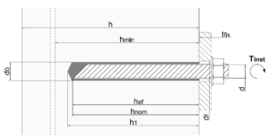
| Installation data and permissible tensile load from the timber base Bar diameter d (mm) | ||||||
| M8 – Ø8 | M10 – Ø10 | M12 – Ø12 | M16 – Ø16 | |||
| h1 | Hole depth | (mm) | 85 | 105 | 125 | 165 |
| d0 | Hole diameter | (mm) | 10 – 12 | 12 – 14 | 14 – 16 | 18 – 20 |
| hnom | Nominal anchoring depth | (mm) | 80 | 100 | 120 | 160 |
| hef | Effective anchoring depth | (mm) | 80 | 100 | 120 | 160 |
| h | Recommended substrate thickness | (mm) | 160 | 200 | 240 | 320 |
| scr | Dual spacing | (mm) | 100 | 125 | 150 | 200 |
| ccr | Distance from edge | (mm) | 80 | 100 | 120 | 160 |
| Smin | Minimum hole centre distance | (mm) | 50 | 50 | 60 | 80 |
| Cmin | Minimum distance from the edge | (mm) | 50 | 50 | 60 | 80 |
| tfix |
Maximum fixable thickness | (mm) | 10 | 20 | 30 | 35 |
| df |
Hole diameter fixable thickness | (mm) | 9 | 12 | 14 | 18 |
| Tnst |
Tightening torque | (mm) | 7 | 15 | 25 | 30 |
| Nrec | Permissible tensile load | (kN) | 3,2 | 4,2 | 6,1 | 10,7 |
| Type and diameter of rod | Hole diameter (mm) | Anchoring hole depth (mm) | Number of fixings (300 ml) | Number of fixings (400 ml) | |
| Threaded rod | M8 | 10 | 85 | ± 60.5 | ± 81 |
| M10 | 12 | 95 | ± 37.5 | ± 50.5 | |
| M12 | 14 | 115 | ± 23 | ± 30.5 | |
| M14 | 16 | 115 | ± 17 | ± 22.5 | |
| M16 | 18 | 130 | ± 12 | ± 16.5 | |
| M18 | 20 | 130 | ± 8.5 | ± 11 | |
| M20 | 24 | 175 | ± 5 | ± 7 | |
| M22 | 26 | 190 | ± 4 | ± 5 | |
| M24 | 28 | 215 | ± 3 | ± 4 | |
| M27 | 30 | 245 | ± 2.5 | ± 3 | |
| M30 | 35 | 275 | ± 1.5 | ± 2 | |
| M33 | 37 | 300 | ± 1 | ± 1.5 | |
| M36 | 40 | 300 | ± 1 | ± 1.5 | |
| M39 | 42 | 360 | ± 1 | ± 1 | |
| Improved adhesion rods | Ø 8 | 12 | 80 | ± 42 | ± 56 |
| Ø 10 | 14 | 100 | ± 25 | ± 33.5 | |
| Ø 12 | 16 | 120 | ± 16 | ± 21.5 | |
| Ø 14 | 18 | 140 | ± 11 | ± 14.5 | |
| Ø 16 | 20 | 160 | ± 8 | ± 10.5 | |
| Ø 18 | 22 | 180 | ± 6 | ± 7.5 | |
| Ø 20 | 25 | 200 | ± 4 | ± 5.5 | |
| Ø 22 | 26 | 220 | ± 3.5 | ± 4.5 | |
| Ø 24 | 28 | 240 | ± 2.5 | ± 3.5 | |
| Ø 25 | 30 | 250 | ± 2 | ± 3 | |
| Ø 26 | 32 | 260 | ± 2 | ± 2.5 | |
| Ø 28 | 34 | 280 | ± 1.5 | ± 2 | |
| Ø 30 | 37 | 300 | ± 1 | ± 1.5 | |
| Ø 32 | 40 | 320 | ± 1 | ± 1.5 | |
| Fixings with cages in hollow bricks | M8 | 12 | 50 | ± 38.5 | ± 51.5 |
| M8 | 12 | 60 | ± 32.5 | ± 43.5 | |
| M8 | 12 | 80 | ± 25 | ± 33.5 | |
| M10 | 16 | 85 | ± 13.5 | ± 17.5 | |
| M10 | 16 | 100 | ± 11.5 | ± 15 | |
| M10 | 16 | 135 | ± 8.5 | ± 11.5 | |
| M10 | 16 | 140 | ± 8 | ± 11 | |
| M14 | 17 | 130 | ± 8 | ± 10.4 | |
| M12 | 20 | 85 | ± 8.5 | ± 11.5 | |
| M16 | 22 | 150 | ± 4 | ± 5.5 | |
| M16 | 22 | 200 | ± 3 | ± 4 | |
| M20 | 30 | 250 | ± 1.5 | ± 2 | |
Contact our team for personalized support and product guidance.